
Wiring the Dynalite Alternator for the T -Type
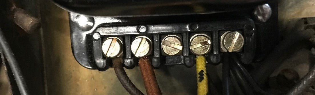
There are wiring instructions included with the Dynalites. Most (if not all) of the wiring changes can be made at the control box (voltage regulator). When using the RB106 5 post regulator, you can keep the regulator in place, just ground the wires that would have gone to the earth terminal (E) to a screw or bolt making good contact with metal.I used the battery ground bolt on the side of the battery box. Feed the A terminal with the D wire from the Dynalite, (moving the D wire from the D terminal to the A grub screw, but leave the small yellow wire on the D grub screw). Feed the A1 terminal thru the 'loop' of the regulator coil. Use the D terminal grub screw to connect the F wire from the Dynalite and the small yellow wire that is originally on the D terminal. That small yellow wire on the D terminal feeds the ignition light. If you are installing a Positive Ground Dynalite, you will need to place the relay (provided) in the ignition light circuit (shown in the included wiring diagram). Negative Ground Dynalites do not need this relay. If you want, you could cut away any connections inside the regulator except the single loop that connects the A terminal to the A1 terminal. There is absolutely no need for either of the coils inside the regulator. The alternator in the Dynalite is internally regulated so there is no need for the voltage regulator (control box). Some owners have fused the connection between the A and the A1 grub screws, this is a worthwhile modification as it protects the wiring harness from excessive amperage draw. (A 20 amp fuse should be sufficient.)


