Installing the Dynalite Alternator

The dynalite is an alternator that has the appearance of the original dynamo (generator) that the T-types originally came with. It is designed to be an exact replacement for the original Lucas Dynamo, with the correct size and mounting holes. It also accepts the pulley and fan from the original dynamo. The unit has a threaded end to mount a tachometer reduction gearbox for attaching the original tachometer cable. There are a few wiring changes that need to be made, as the alternator has an internal regulator so the original voltage regulator (control box) is not needed. Complete directions and a wiring diagram showing the orignal configuration and the new configuration needed are included with the Dynalite. The Dynalite is available in either Postitve Ground or Negative Ground configuration (they are not interchangable, they must be ordered in the configuration for your particular car).
Please note, this installation was done this way because I wanted to use the car's existing wiring harness, age unknown. I only ran new wires for the ammeter and voltage regulator so that I could fuse those circuits for protection. If you have recently installed a new wiring harness or in the process of restoring your car and will be installing a new wiring harness, then you would only need to make a few connection changes at the voltage regulator to install the Dynalite. There is no need for extra wiring, etc., as nothing in a T-type will draw more power than a standard new wiring harness can handle. (Of course for positive ground cars you will have to install the relay inline with the ignition light feed, that is all. Negative ground cars do not even need that relay.) So don't be scared off by this procedure as described below, this was a special case for this car only.
Since this is a new product, I decided to install one in our 1952 MG TD. I really did not want to put it in the TD, as the dynamo and regulator had always worked perfectly in that car. I have never had a dead battery or any issue with the electrical system, and had recently switched over the car to LED wing lights, tail light and headlights, so it did not need a larger capacity dynamo of alternator. But I like to understand the products we sell when I can, so the TD had to take one for the team!
Working on automobiles can have some dangerous consequenses. Before attempting to modify the electrical system of your car be sure you understand its intended function and the intention of the modifications you intend to do. Proceed at your own risk, electrical components like this are not returnable once installed.
Since the TD is wired positive ground, I went ahead with installing the positive ground version. The positive ground Dynalite requires a relay to be wired into the wire from the ignition key to the ignition light. The wiring diagram clearly shows how this should be done.The wiring diagram does not tell you how to find this wire, or get to it under that dash! But it is obvious once you locate the ignition light, it should have a white wire on one side of it. This is the wire that needs to be connected to the relay and then from the relay back to the ignition light. Here is a photo of the relay mounted under the dash.

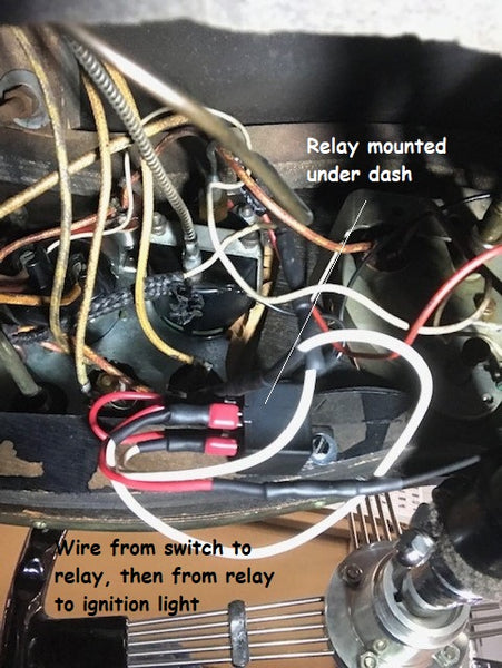
The relay also needs a ground wire, to be sure it was grounded I used one of the bolts on the underdash "hoop".

Once the relay is wired up, there were a few more changes to the wiring I needed to do. The directions that come with the Dynalite say to be sure the wiring from the main alternator feed to the battery must be rated at 40 amps minimum. Since this car seems to have an original (or at least old) wiring harness, the condition of the wires from the dynamo to the battery are really unknown. So I decided to run new wires from the Dynalite to the control box, and from the control box to the ammeter and then on to the battery. (The battery connection is actually made at the starter switch, check the wiring diagram.) Personally I think the 40 amps figure is a bit excessive, there is nothing in this car that is going to draw 40 amps except a dead short, but this is the figure the manufacturer recommends.
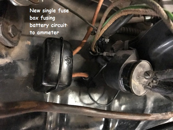
Almost all of the wiring modifications can be made in the location of the control box. Since the control box (voltage regulator) is not needed with the Dynalite, the control box is basically repurposed to be a junction box. The wires from the original dynamo come to the control box, and the wires from the ammeter also terminate at the control box as well. I used a non-functioning control box that I just removed the two coils, and then fused the connection between the A terminal and the A1 terminals. All the other connections were cut or removed. I used the E terminal as a grounding terminal for the original harness, and grounded that to the same bolt as the battery ground wire. See pictures below:


I chose to fuse the circuit at 15 amps, this may need further testing, if 15 is not enough I will go to 20 amps, but as previously stated, I think 15 is plenty for this car. This is just personal preference on the size of the fuse, but I certainly think the circuit should be fused. At this point I marked all the original wires at the control box and removed them from the control box, and removed the control box from the bulkhead. The A1 wire, the small wire at the D terminal (for ignition light) and the ground wire group will be reused, the D, F and A wires will be replace with new wires. Notice that there are 2 wires on the D terminal, the larger one is from the dynamo, and the smaller is the one that runs to the ignition light, this will be important later.

Now on to the rewiring. I was not going to use the original wires in the harness, so the decision was made to run new wires of a heavier gauge on the Dynalite to battery circuit. I installed the Dynalite in place of the dynamo, reusing the fan and pulley from the old dymamo, and removing and marking the D and F wires from the old dynamo (these will not be reused).

Here is where you have to pay close attention to the new wiring diagram included with the Dynalite. Once he Dyalite was installed, I ran a new wire from the D terminal on the Dynalite and from the F terminal on the Dynalite back to the new control box. The new control box is being used as a junction box. The D wire from the Dynalite will go to the A terminal. The F wire from the Dynalite will go to the D terminal on the new control box. Confused? I'll try to explain. Since the power coming from the Dynalite is already "regulated" it can go directly to the main battery feed, which is the A terminal. The F terminal on the Dynalite needs to go to the ignition light on the dash. Originally the smaller wire on the D terminal of the control box fed the ignition light, and it will be reused here. So the F wire from the Dynalite needs to connect to the old smaller wire on the D terminal and pass thru to the ignition light. The easy way to do this is to put the smaller original wire that was on the D terminal at the control box back on the D terminal and attach the new F wire from the Dynalite to it using the D terminal grub screw. At this point the original A1 wire can be reattached to the A1 terminal on the new control box. Also the ground wires that were on the E terminal of the old control box can go on to the E terminal on the new control box and the new ground lead can be connected to the same bolt as the battery ground cable.
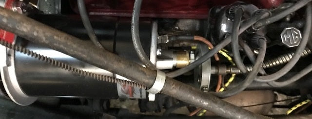
Now the the Dynalite to control box wiring is finished. Next we need to get the battery into the circuit with some new bigger wire. To do this correctly, we need to back the dashboard out a bit, unless you like to lie on your back to connect up the ammeter. I found removing the screws, glove box hinges, and disconnecting the tach and speedo cables gave me enough slack to get the dash out about 3 inches, not great, but good enough. The entire battery feed to the car runs through the ammeter. The battery negative terminal runs to one side of the starting switch, from there it runs back to both the fuse block and the A terminal on the old control box. So I will run a new bigger wire from the starter lug back to the Ammeter, bypassing the old wire in the harness. I will leave the wire from the starter lug that goes over to the fuse box, as that is not in the circuit I am concerned with. Unfortunately the wiring harness in the car has both the ammeter feed and the fuse block wires connected to one ring terminal, so I needed to separtate them an determing which is the ammeter feed and which is the fuse block feed.

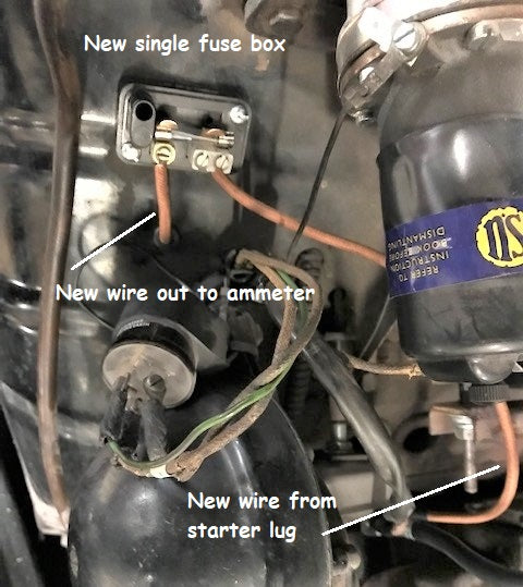
Once I determined which is the ammeter feed, I attached a new ring terminal to the wire that fed the fuse block, and clipped the other wire and insulated the end. Then I ran a separate new bigger wire from the starter lug over to a small single fuse box, and then on to the ammeter. I had to make a new hole in the bulkhead and install an insulating grommet. This may be the "belt and suspenders" logic, but I think the wire from the starter lug to the ammeter should be fused before it gets under the dash. That wire is a direct feed from the battery, and running it up behind the dash unfused in not, in my opinion, a smart idea. It is only attached to the ammeter by a grub screw, and you don't want that wire coming loose behind the dash!
Now this wire runs into the car, under the dash and up to one side of the ammeter, replacing the original wire (which I insulated and removed from the ammeter).
Same thing with the other original wire on the other terminal of the ammeter, I insulated it and removed it from the ammeter. From that other terminal of the ammeter, I ran a new bigger wire back out under the dash, up thru a new hole and grommet and on to the new control box A terminal. (Same terminal as the new D wire from the Dynalite). Here is a photo of the ammeter in the dash with the new bigger wires.

Here is a picture of the new control box with all the connections.

Cover on and ready to go

New fused battery circuit.