

“The Control Box”, Voltage Regulator, Adjustments
What we refer to as the “voltage regulator”, more aptly called “Control Box” by the British, is often a source of great mystery to many British Car owners. The Control Box is actually quite a simple and yet remarkably clever electromechanical device.
There is a very detailed description of how to set and adjust a control box in the original Workshop Manual, and I will not attempt to describe it in such detail here. I highly recommend you read the electrical section of the manual before attempting to work on either the Control Box or the Generator. Rather this tip will attempt to point out the various parts of the control box, how they work, and how they are adjusted. Keep in mind that you are working with 50 plus year old equipment in most cases, and the original parts are no longer easily available. Also remember that the Control Box ‘regulates’ the generator output, so adjusting the Control Box can definitely effect the generator’s performance, some times fatally!
The Control Box in simple terms controls two functions of the car’s electrical system.
- Connects or disconnects the battery from the charging circuit.
- Regulates the output of the generator.
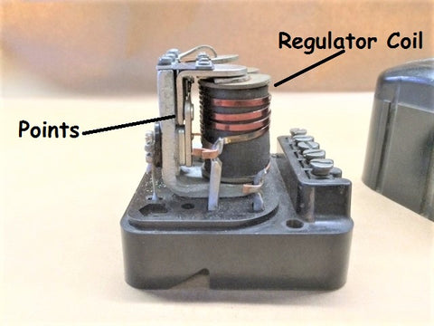
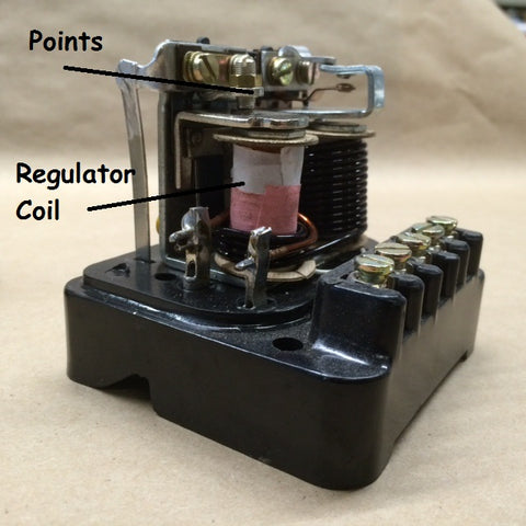
One, it controls when the battery is in the charging circuit (the battery is always in the electrical circuit of the car, but not always in the charging circuit). It does this by opening and closing a connection (a set of points) in the Control Box that make or break the connection between the battery and the generator. The opening and closing of these ‘points’ is controlled by one of the two coils in the control box, the one on the right (larger wire and more windings).
This coil becomes an electromagnet when the generator begins to spin and produce voltage. As the voltage on the D (dynamo) terminal of the Control Box increases, so does the strength of the electromagnet, eventually closing the set of contacts (points) and putting the battery in the charging circuit. Alternately, when the generator stops spinning, or just slows down, and stops producing a high enough current, the electromagnet loses its strength and the contacts (points) open, removing the battery from the charging circuit. This set of contacts mostly stays closed when the car is in motion and the generator is spinning, and producing voltage above roughly 10 to 11 volts. This is referred to as the ‘cutout’ voltage, (I think it should be called the ‘cut-in’ voltage, as above 10 volts the battery is cut-in to the charging circuit). This function is important to the car as it prevents the battery discharging when the engine is not running, which can damage the generator as the battery grounds though the generator when the generator is not producing voltage. Opinions vary with what to set the cutout voltage to, but most set it between 10 and 12 volts, once the generator is spinning it should be above 10 volts easily, and when it is not producing at least 10 volts, you want the battery out of the charging circuit.
Second, the Control Box regulates the output of the generator. The output of the generator is controlled by ‘regulating’ the voltage supplied to the field windings of the generator. The generator needs current to produce more current as the field windings require voltage to become magnets. When the generator begins to spin, there is enough residual magnetism in the field windings to produce some current, but as it spins faster it quickly produces enough current to supply the windings. As the generator continues to spin, it continues to produce stronger current, higher voltage, creating a ever stronger magnetic field, and ever more voltage. An unregulated automobile generator can produce more than 50 volts! This is not good for the generator, obviously, so the current output of the generator must be ‘regulated’. This ‘regulation’ is controlled by the other coil in the control box, the one on the left, (less windings, thinner wire).
There is a set of contacts on the second coil that control the voltage out to the Field Windings, this is the F terminal on the Control Box. This set of contacts works the opposite of the ‘cutout’ coil, in that they are initially closed, supplying current to the generator. This coil is also an electromagnet, and as the voltage from the generator increases, the magnet becomes stronger, eventually pulling ‘opening’ the contacts (points) and reducing (it does not cut it off entirely) the flow of current to the Field Windings and reducing the output of the generator. As you can imagine, this set of contacts opens and closes hundreds of times a second and the voltage from the generator is constantly increasing. These contacts (points) buzz when in operation as they are constantly being opened and closed by the electromagnet of the regulator coil. This opening and closing of the points ‘regulates’ the current to the field coils, and subsequently decreases the generator’s output. With in a millisecond however, the generator’s output drops, the coil’s electromagnetic strength decreases, and the points reconnect, supplying the Field Windings with current, increasing the current strength. This cycle is repeated as long as the generator is producing current.
Both of the coils in the Control Box are adjustable for their cut out or cut in voltage, this is described in more detail in the Workshop Manual. The photos below show the contacts and the set screws for adjusting the voltage through the coils. The set screws and points are similar in both the original 5 post RB106 and and the early style 9 post RF95 Lucas Control boxes. Also shown are some photos of the current replacement style 5 post regulator that we currently sell as a replacement for the RB106.
This tip is intended to explain the function of the Control Box. Now that you know the function of the Control Box, I might add that it rarely needs adjustment, the most common problem with the control box is after sitting unused for a long duration, the contact points can oxidize and need to be cleaned lightly with very fine emery cloth or 600 paper.
As stated above, be sure you know what you are adjusting, a poorly adjusted Control Box can ruin a generator in a very short time. Read the Workshop Manual before proceeding, and always be sure the generator is in good operating condition, and the battery is fully charged before making changes to the Control Box.
 |
 |
 |
 |
 |
 |
 |
 |